
News
Position:Home > News > Application
With the advancement of dual-carbon goals, electric vehicle on-board chargers (hereinafter referred to as "OBCs") are developing in the direction of two-way energy transmission. They can both obtain power from the grid and feed power back to the grid.
Electric vehicles equipped with two-way OBC can use the remaining power to charge depleted electric vehicles, and can also serve as 220V power sources outdoors. They can also be used as distributed energy storage stations to help the power grid reduce peaks and fill valleys.
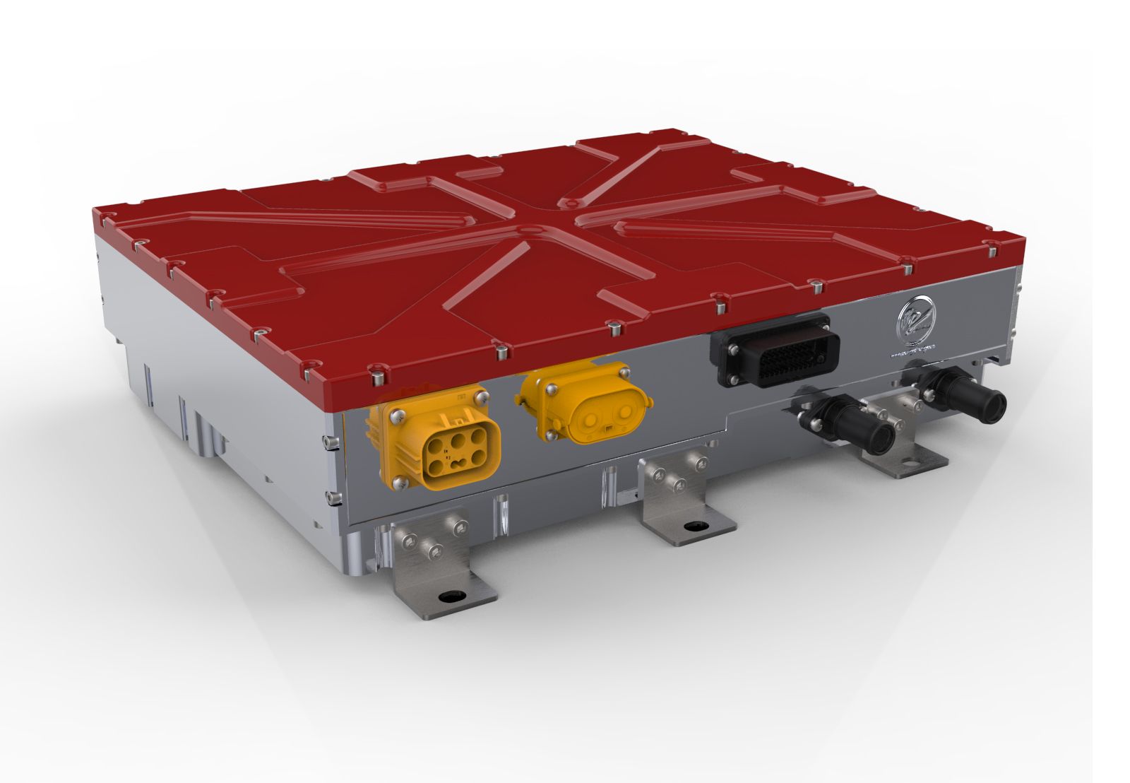
In this article, we take a 6.6kW bidirectional OBC as an example to discuss the application of CLLC topology in bidirectional OBC.
Isolated DCDC is one of the important parts of OBC. LLC topology is used in many one-way OBC isolation DCDC stages. For example, the one-way OBC developed and produced by Dilong New Energy uses LLC topology, which has high energy efficiency and anti-EMI performance. Good, high reliability and other advantages.
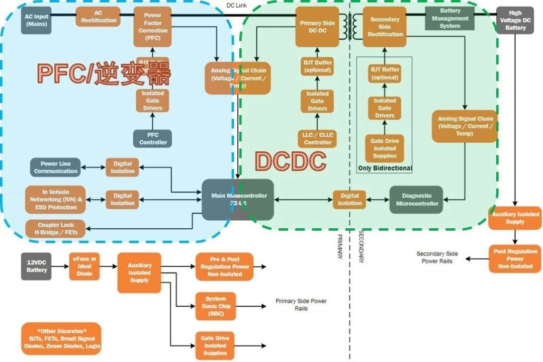
The isolated DCDC stage in the bidirectional OBC will use the CLLC topology.
It replaces the bridge rectifier diode on the battery side in the LLC topology with an active bridge, and then connects a C in series with the battery end of the transformer to ensure magnetic balance.
When charging the battery, the bridge on the left acts as an active switch and the bridge on the right acts as synchronous rectifier; when the battery inverts outward, the bridge on the right acts as an active switch and the bridge on the left acts as synchronous rectifier.
The CLLC topology uses pulse frequency adjustment to control the gain.
It inherits the advantages of the LLC topology and also has soft switching characteristics, high energy efficiency, good anti-EMI performance, low development difficulty, and easier mass production and application of bidirectional OBC.
Below we take a 6.6kW bidirectional OBC CLLC topology as an example to help designers solve challenges in the development process.
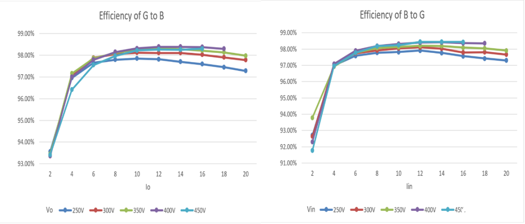
This bidirectional OBC uses a wide bus voltage range to respond to changes in battery voltage, with a peak energy efficiency of up to 98%. It mainly consists of three main parts.
As shown in Figure 3, the big board in the middle is the power board, and all high-voltage and high-current lines will be on this board. The upper right corner is the control board, which is connected to the power board through connectors to facilitate switching between different power solutions. Cross test; on the left is the resonant cavity combination, which contains a transformer with integrated resonant inductor and two resonant capacitor plates.
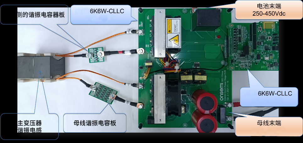
The three main parts of the resonant capacitor are composed of multiple MLCCs connected in series and parallel, which can meet the requirements of withstand voltage and current to achieve smaller size. The resonant cavity can be disassembled to facilitate designers to verify the parameters of different transformers, inductors and capacitors.
This solution includes a radiator, fan, auxiliary power supply, protection circuit, etc. By directly connecting the power supply and load, it can be tested for a long time under full load.
In the power board, the two active bridges located on the bus side and the battery side are composed of four 1200V/40 milliohm NVHL040N120SC1 and four 900V/20 milliohm NVHL020N90SC1 silicon carbide MOS. Compared with Si, silicon carbide (SiC) can Achieve higher power density, higher switching frequency and extremely efficient design.
These eight SiC MOS are driven by eight magnetically isolated high-current drivers. The drive signals are sent from the control board through the control interface. All signals of the control interface are located on the battery side, and the level does not exceed 12V.
After the voltage and current at the battery end are sampled, they are divided and amplified and sent directly to the control interface; the voltage sampling on the bus side is completed by an independent ADC, and the data is transmitted to the control interface through the SPI bus and the digital signal isolator.
In the control panel, this OBC uses an automotive grade LLC control chip for pulse frequency modulation (hereinafter referred to as "PFM") and synchronous rectification control; it uses a low-power MCU for constant voltage charging For value setting, a vehicle-grade rail-to-rail operational amplifier is used for constant current charging control, and a vehicle-grade logic device is used to determine and convert the direction from the grid to the battery and from the battery to the grid.
If you want to save costs, you can replace 1200V and 900V SiC MOS with 900V and 650V SiC MOS, but you need to control the switching spikes. It is best to start by reducing the PCB parasitic inductance, which can be achieved by adding bypass capacitors.
Since SiC MOSFET devices with high voltage and low Rdson have a large Qg, in order to maintain high efficiency at high switching frequencies, they must be driven by high-current gate drivers.
In addition, the control interface of this solution is located on the battery side, and the MOS on the drive bus side must be isolated and comply with safety regulations.
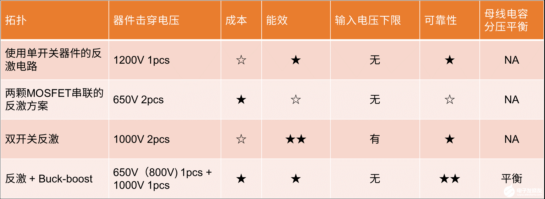
The auxiliary power supply of this 6.6kW bidirectional OBC adopts the "flyback + Buck-boost" topology, which is used to cope with bus voltages up to 750V. As shown in Table 1, compared with the other three topologies, this flyback + Buck-boost topology is superior in terms of cost, energy efficiency, input voltage lower limit, reliability and bus capacitance voltage division balance.

We mentioned earlier that an LLC controller is used in the control panel for PFM loop and synchronous rectification control. This controller uses current mode, has fast loop response, is not easy to oscillate, and has a dual-edge tracking synchronous rectification control function.
A period of PWM operating mode is inserted between the PFM mode and the intermittent operating mode in order to improve the energy efficiency and voltage ripple under light load, and its protection function is also very powerful. It is worth emphasizing that this double-edge tracking synchronous rectification The control method has been proven by the market and is very reliable.
The OBC of new energy electric vehicles is developing in the direction of two-way energy transmission to coordinate with the advancement of dual-carbon goals. Dillon New Energy has not only achieved impressive results in the one-way OBC market, manufacturing and supplying one-way OBC products to more than 400 manufacturers and customers around the world, but also continues to make breakthroughs in the two-way OBC field.
At present, Dillon 22kW bidirectional OBC is in the research and development stage and is about to emerge in the market. It complies with GB/T18487.1_2015, IEC61851.1_2017 and SAE J1772_2017 standards. This bidirectional OBC product has more power than the 6.6 kW bidirectional OBC mentioned above. Larger, more energy efficient, and with a wider range of applications, let's look forward to its launch.